Basic Radio Propagation Theory (062.01)
Basic Principles (062.01.01)
Electromagnetic waves (062.01.01.01)
State that radio waves travel at the speed of light, being approximately 300,000 km/s (062.01.01.01)
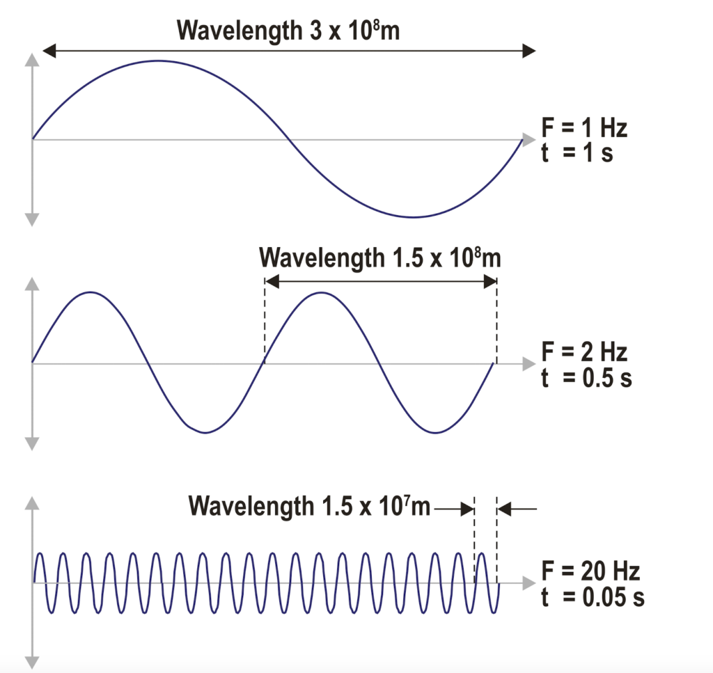
Define a cycle. A complete series of values of a periodical process (062.01.01.02).
Define Hertz. One Hertz is one cycle per second (062.01.01.03).
Frequency, wavelength, amplitude, phase angle (061.01.01.02)
Define frequency. The number of cycles occurring in one second expressed in Hertz (Hz).
Define wavelength. The physical distance travelled by a radio wave during one cycle of transmission.
A radio wave is a changing electromagnetic wave which moves away from an aerial/ antenna at the speed of light.
The speed of light is constant (in a vacuum) at 300,000,000 m/s (3 x 10⁸ m/s).
Electromagnetic waves are referred to in terms of:
- Wavelength;
- Frequency;
- Amplitude;
The wavelength is defined as the length of one complete cycle of a wave, and is represented by the letter λ (measured in units of length – meters).
| kilohertz | kHz | 1,000 Hz |
| megahertz | MHz | 1,000,000 Hz |
| gigahertz | GHz | 1,000,000,000 Hz |
Define amplitude. The maximum deflection in an oscillation or wave.
No information
State that the relationship between wavelength and frequency is: wavelength (λ) = speed of light (c) / frequency (f)
The frequency is defined as the number of cycles the wave makes in a second, and is measured in the unit hertz (Hz).
The relationship between wavelength and frequency is expressed by the formula:
λ = speed of light (c) / frequency (Hz)
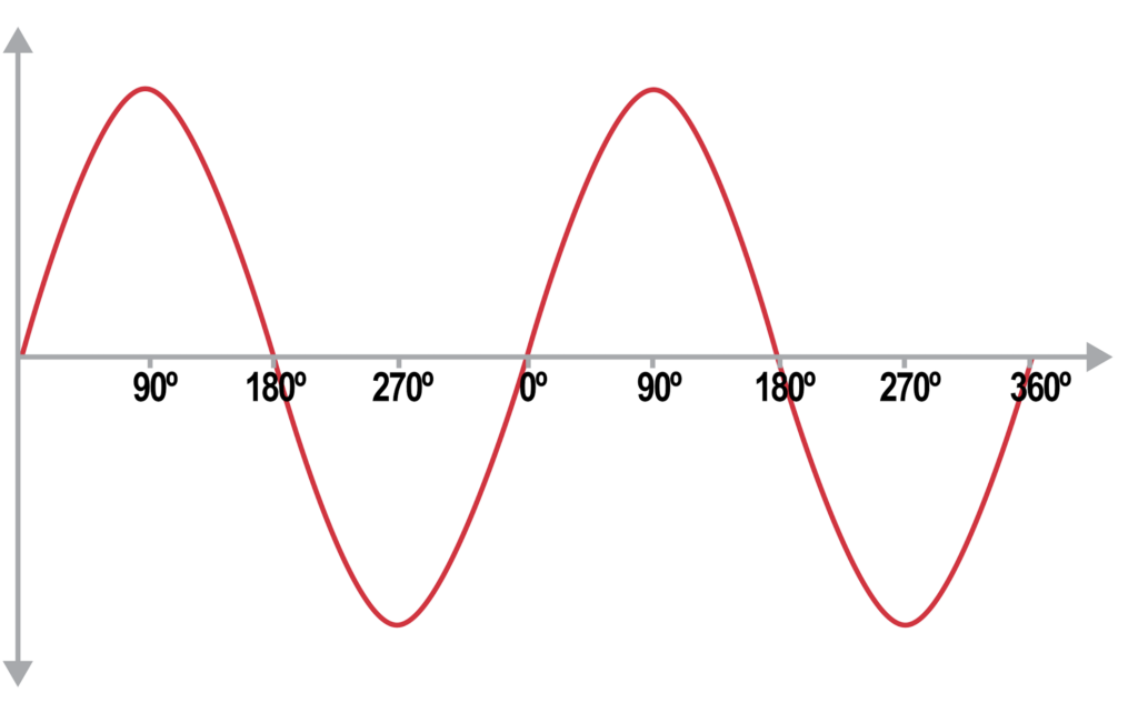
Define phase. The fraction of one wavelength expressed in degrees from 000° to 360°.
Positions on a radio wave are described in degrees from 0° to 360°, called the phase angle. By convention, the phase is 0° where the amplitude is zero and rising.
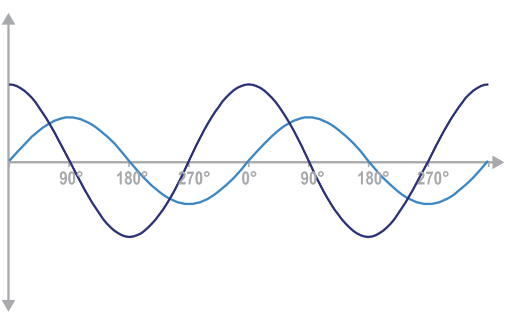
Define phase difference/shift. The angular difference between the corresponding points of two cycles of equal wavelength, which is measurable in degrees.
If two transmissions with the same wavelength (and thus frequency) start at the same point, the waves will be synchronized and in phase. If one starts (slightly) after another, they will be out of phase by an amount measured in degrees. Or in other words there is a phase difference / shift between the two waves.
Frequency bands, sidebands, single sideband (061.01.01.03)
List the bands of the frequency spectrum for electromagnetic waves: Very Low Frequency (VLF); 3 – 30 kHz Low Frequency (LF); 30 – 300 kHz Medium frequency (MF); 300 – 3000 kHz High frequency (HF); 3 – 30 MHz Very high frequency (VHF); 30 – 300 MHz Ultra high frequency (UHF); 300 – 3000 MHz Super high frequency (SHF); 3 – 30 GHz Extremely high frequency (EHF) 30 – 300 GHz (062.01.01.03.01).
The radio spectrum is part of the electromagnetic spectrum that has frequencies from 3 kHz to 300 GHz. Within these bounds it is broken down into the following eight (8) bands:
| Band | Frequency | Wavelength | |
|---|---|---|---|
| VLF | Very Low Frequency | 3 kHz – 30 kHz | 100 km – 10 km |
| LF | Low Frequency | 30 kHz – 300 kHz | 10 km – 1 km |
| MF | Medium Frequency | 300 kHz – 3 MHz | 1 km – 100 m |
| HF | High Frequency | 3 MHz – 30 MHz | 100 m – 10 m |
| VHF | Very High Frequency | 30 MHz – 300 MHz | 10 m – 1 m |
| UHF | Ultra High Frequency | 300 MHz – 3 GHz | 1 m – 10 cm |
| SHF | Super High Frequency | 3 GHz – 30 GHz | 10 cm – 1 cm |
| EHF | Extremely High Frequency | 30 GHz – 300 GHz | 1 cm – 1 mm |
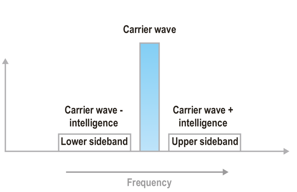
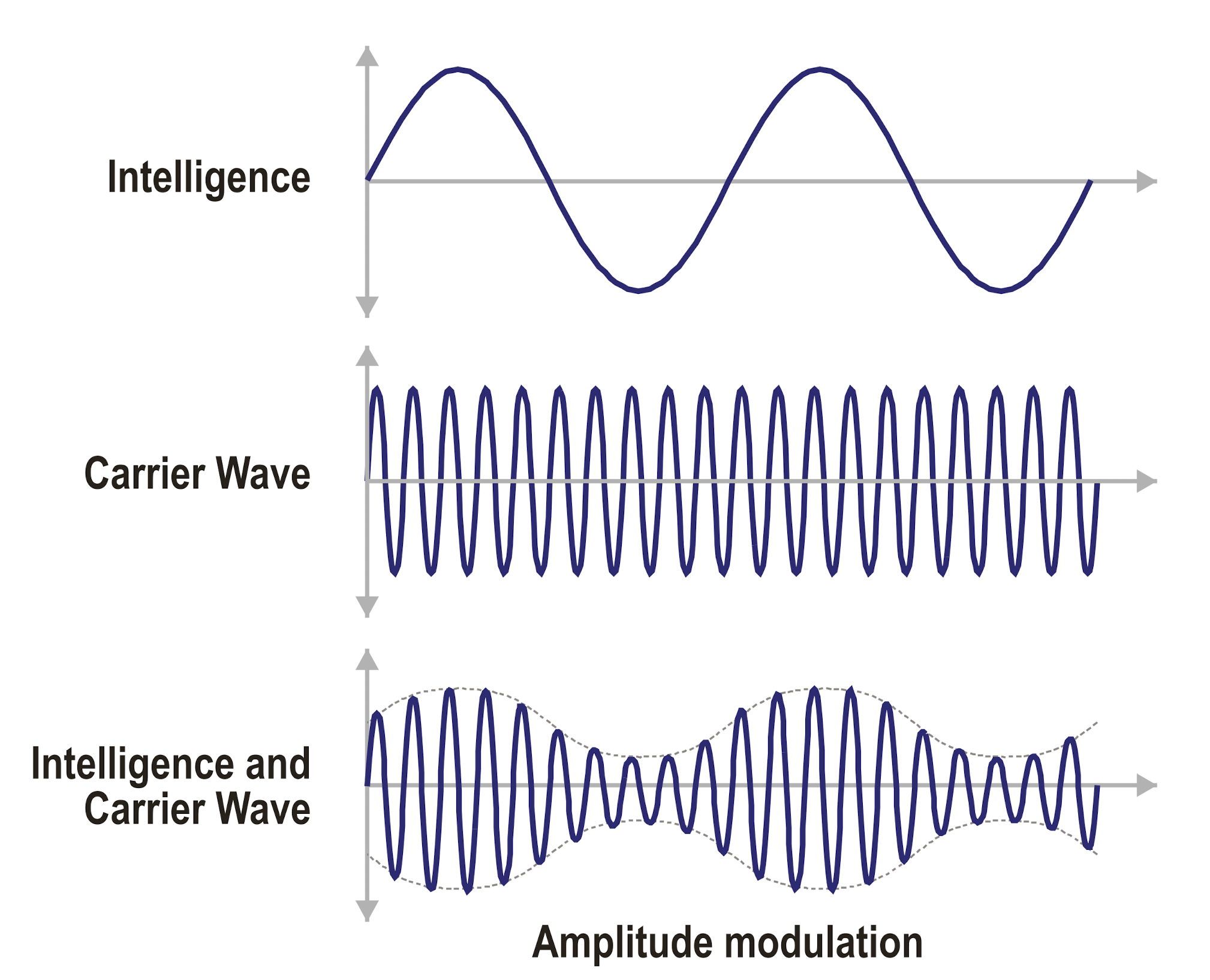
State that when a carrier wave is modulated, the resultant radiation consists of the carrier frequency plus additional upper and lower sidebands (062.01.01.03.02).
Modulation is the process of adding and transporting information by a carrier radio wave (see 062.01.01.05.03) and uses a process called heterodyning to add (impose) the intelligence on the carrier wave.
It creates two new frequencies alongside the original carrier wave, the carrier wave plus the intelligence and the carrier wave minus the intelligence.
These extra frequencies are called sidebands, the upper sideband at the higher frequency and the lower sideband at the lower frequency.
In example: when an Amplitude Modulated signal is created from a carrier wave of 400 kHz and intelligence (perhaps a voice signal) of 1 to 3 kHz, then the result is:
- The original carrier wave of 400 kHz;
- The upper sideband between 401 kHz and 403 kHz (400 + 1 to 400 +3);
- The lower sideband between 397 kHz and 399 kHz (400 – 3 to 400 – 1);
Question alarm: based on this example remember “modulation is the addition of a low frequency signal (tone, voice) to a high frequency carrier wave“. Not the other way around.
State that HF Volmet, and HF two-way communication use a single sideband (062.01.01.03.03).
As heterodyning produces two sidebands including the intelligence, it is possible to reduce the amount of bandwidth taken by the transmission and subsequently reduce the required power of the transmitter, by deliberately not transmitting the carrier wave and one of the sidebands.
This is called a single sideband (SSB) transmission.
In order to optimize the range, this technique is particularly used in HF long range communications.
State that a radio signal may be classified by three symbols in accordance with the ITU Radio Regulation vol.1: e.g. A1A – First symbol indicates the type of modulation of the main carrier – Second symbol indicates the nature of the signal modulating the main carrier – Third symbol indicates the nature of the information to be transmitted (062.01.01.03.04).
Radio transmissions are classified by a three digit ITU code. The symbols indicate:
- the type of modulation of the main carrier;
- the nature or type of the signal modulating the main carrier;
- the type of information carried;
The designators that could come from Non-Directional Beacons (NDBs) are part of the Learning Objectives (062.02.02.01.17) and classified as:
N0N: carrier without modulation;
A1A: carrier with keyed Morse code modulation;
A2A: carrier with amplitude modulated Morse code;
| First symbol | |
|---|---|
| N | Unmodulated carrier |
| A | Double sideband |
| F | Frequency modulation |
| G | Phase modulation |
| P | Unmodulated pulses |
| Second symbol | |
| 0 | No modulation |
| 1 | Digital information |
| 2 | Modulated digital information |
| 3 | Analogue information |
| 7 | Multi channel digital information |
| 8 | Multi channel analogue information |
| 9 | Composite digital and analogue information |
| Third symbol | |
| N | No information |
| A | Morse |
| E | Voice |
| W | Morse and Voice |
Pulse characteristics (062.01.01.04)
Carrier, modulation (062.01.01.05)
Define carrier wave. The radio wave acting as the carrier or transporter (062.01.01.05.01).
Define keying. Interrupting the carrier wave to break it into dots and dashes (062.01.01.05.02).
Define modulation. The technical term for the process of impressing and transporting information by radio waves (062.01.01.05.03).
Any information to be transmitted must be laid on top of the carrier wave before transmission and decoded on reception. This process is know as modulation and demodulation.
Modulation is the process of adding (impressing) and transporting information by a carrier radio wave.
Modulation can be achieved by changing the amplitude, the frequency or the phase of the carrier wave. Each method has its advantages and disadvantages.
Kinds of modulation (amplitude, frequency, pulse, phase) (062.01.01.06)
Define amplitude modulation. The information is impressed onto the carrier wave by altering the amplitude of the carrier (062.01.01.06.01).
The simplest form of modulation is to vary the amplitude of the carrier wave to transmit information.
Define frequency modulation. The information is impressed onto the carrier wave by altering the frequency of the carrier (062.01.01.06.02).
Describe pulse modulation. A modulation form used in radar, by transmitting short pulses followed by larger interruptions (062.01.01.06.03).
Describe phase modulation. A modulation form used in GPS where the phase of the carrier wave is reversed (062.01.01.06.04).
Antennas (062.01.02)
Wave propagation (062.01.03)
Structure of the ionosphere and its effect on radio waves (062.01.03.01)
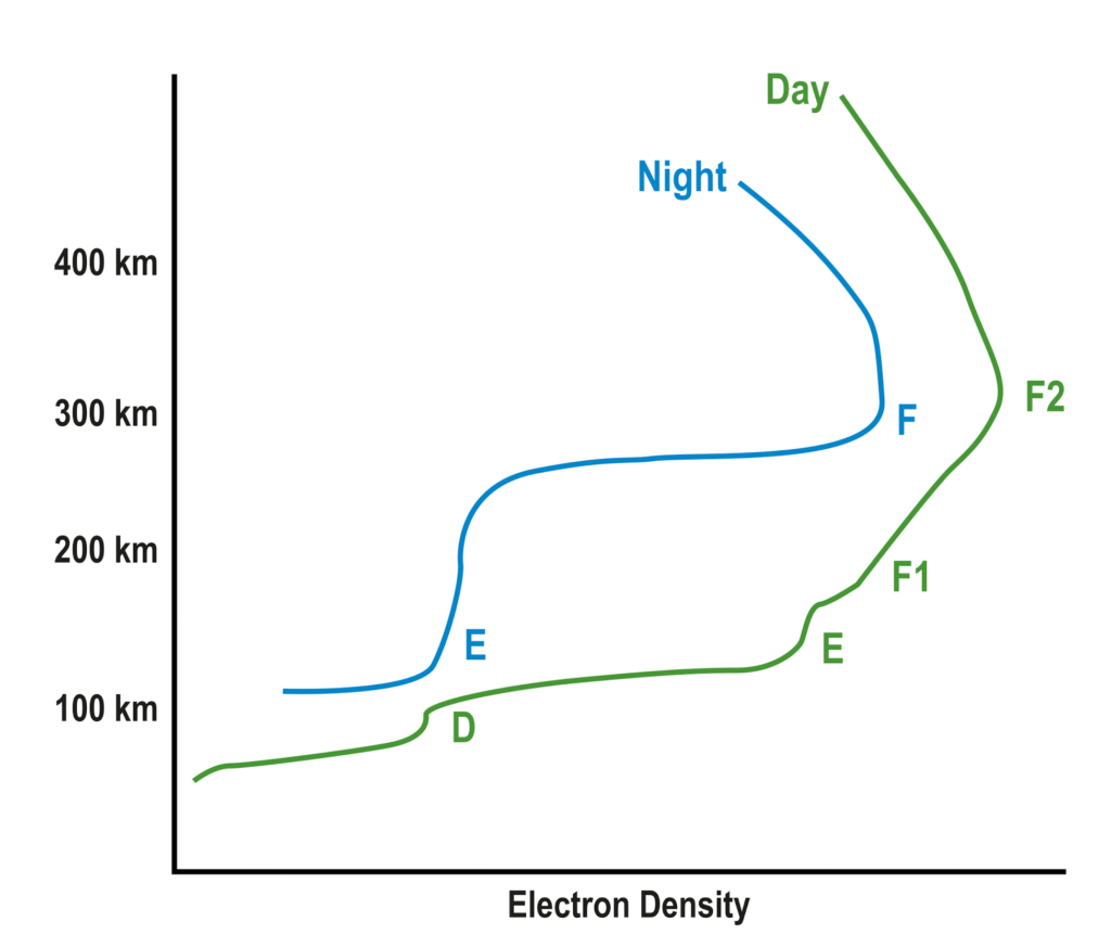
State that the ionosphere is the ionised component of the Earth’s upper atmosphere from approximately 60 to 400 km above the surface, which is vertically structured in three regions or layers (062.01.03.01.01).
State that the layers of the ionosphere are named D, E and F layers, and their depth varies with time (062.01.03.01.02).
The ionosphere is the ionised component of the Earth’s atmosphere, stretching from approximately 60 to 400 km above the surface and is divided in three layers: D, E and F.
In the Ionosphere the (few) gas molecules that are present are being bombarded with solar and cosmic radiation, which split the molecules into positively and negatively charged ions. The amount of ions / density of ions increases with the intensity of radiation.
The density is higher in the upper ionosphere (F), as these molecules are subject to a higher intensity of radiation, than those in the lower (D / E) ionosphere. Furthermore, as solar radiation is absent at night, the density of the ionosphere is less at night in comparison to daytime.
As such the density of the layers vary with time of day, season and solar activity.
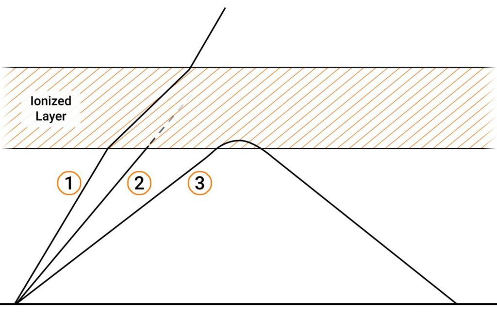
State that electromagnetic waves refracted from the E and F layers of the ionosphere are called sky waves (062.01.03.01.03).
Radio waves will be refracted at the boundary where the ion density changes (E & F layer). At low frequencies and at the correct angle of incidence the radio wave will be refracted enough to return back to Earth, these radio waves are called Sky waves.
Explain how the different layers of the ionosphere influence wave propagation (062.01.03.01.04).
No information
Ground waves (062.01.03.02)
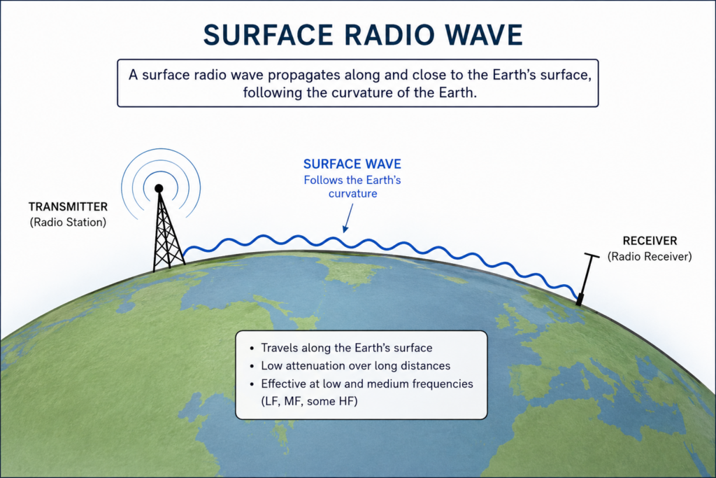
Define ground or surface waves. The electromagnetic waves traveling along the surface of the Earth (062.01.03.02.01).
Surface waves or ground waves are radio waves which tend to follow the curvature of the Earth due to diffraction ( see 062.01.03.06.05 ).
As diffraction is greatest at low frequencies, surface waves form at the low frequency end of the radio spectrum.
The distance a surface wave can travel is limited by surface attenuation, which is as well lowest at lower frequencies.
These two factors mean that surface waves are longest at the lowest frequencies.
Space waves (062.01.03.03)
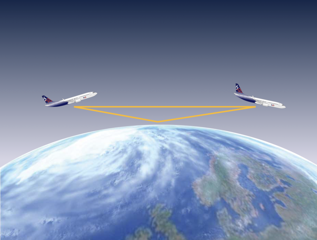
Define space waves. The electromagnetic waves traveling through the air directly from the transmitter to the receiver (062.01.03.03.01).
Space waves are line of sight waves.
Naming is not intuitive. A reverse definition between sky and space waves would have been more applicable. So don’t mix them up!
Space waves are the only propagation path for frequencies in the range from higher VHF to EHF.
Max theoretical range. = 1.23 x √H1 + 1.23 x √H2
(H1 height of the transmitter, H2 height of the receiver (in feet above mean sea level))
Propagation with the frequency bands (062.01.03.04)
State that radio waves in VHF, UHF, SHF and EHF propagate as space waves (062.01.03.04.01).
Radio waves at VHF, UHF, SHF and EHF are certainly subject to refraction as they pass through the ionosphere, but are not bent (refracted) enough to come all the way back to Earth. So, radio waves with frequencies at VHF and higher normally don’t tend to propagate as sky waves.
In addition, at frequencies at VHF and higher the radio waves are not subject to diffraction, therefore not propagating as ground waves either.
Radio waves in VHF, UHF, SHF and EHF only propagate as space waves.
State that radio waves in LF, MF and HF propagate as surface/ground waves and sky waves (062.01.03.04.02).
The frequencies of radio waves in the LF, MF and HF bands are low enough to be subject to both refraction in the ionosphere as the diffraction at the ground.
Doppler principle (062.01.03.05)
Factors affecting propagation (062.01.03.06)
Define Skip Distance. The distance between the transmitter and the point on the surface of the earth where the first sky return arrives (062.01.03.06.01).
State that skip zone/dead space is the distance between the limit of the surface wave and the sky wave (062.01.03.06.02).
Describe ‘fading’: when a receiver picks up two signals with the same frequency, and the signals will interfere with each other causing changes in the resultant signal strength and polarisation (062.01.03.06.03).
State that radio waves in the VHF band and above are limited in range as they are not reflected by the ionosphere and do not have a surface wave (062.01.03.06.04).
Describe the physical phenomena ‘reflection’, ‘refraction’, ‘diffraction’, ‘absorption’ and ‘interference’ (062.01.03.06.05).
Radio waves can lose their energy and be bent or reflected to change their path through the atmosphere.
Bending
Bending can be caused by either refraction or diffraction.
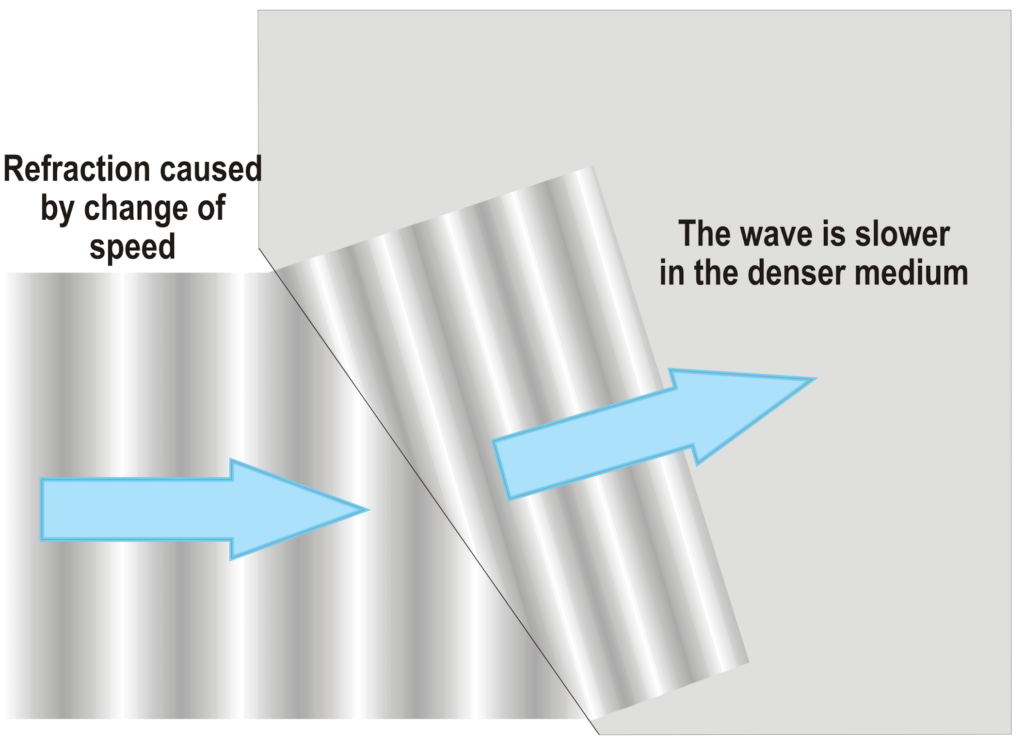
Refraction
Refraction is the change of direction of a radio wave caused by a change of speed due to the difference in optical density between the surface it passes over or the medium it passes through.
The amount of refraction depends on the change in speed of the wave, its frequency and the angle at which it hits the new medium.
In the ionosphere refraction is greater at low frequencies.
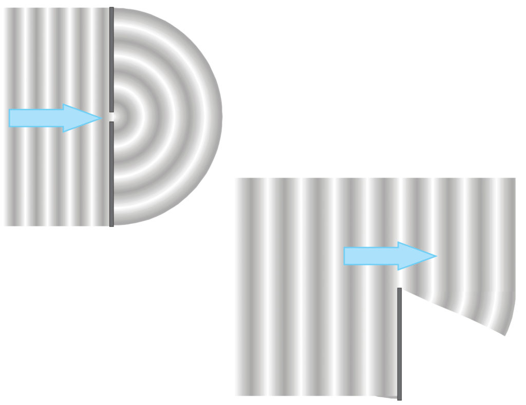
Diffraction
Diffraction is the change in direction of a radio wave when it moves over a sharp object or through a hole.
In the later, the hole will act like a point source and effectively retransmits the wave.
Diffraction is greater at low frequencies.
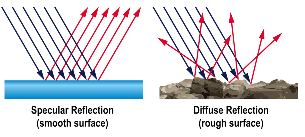
Reflection
Reflection is a radio wave bouncing off a surface (like a mirror reflecting light).
How the radio waves are reflected depends on the angle of attack, the density of the material and how smooth the reflecting surface is; rough surfaces scatter energy in all directions, smooth surfaces act like a mirror.
Whether or not a surface acts like a mirror depends on the wavelength of the radio wave. A surface might appear smooth for a wavelength in the order of a meter, but may not be smooth for a wavelength of a millimeter.
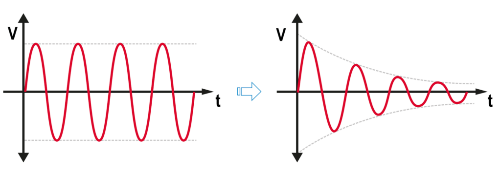
Attenuation
Attenuation is the loss of signal strength (power) of a wave.
Atmospheric attenuation
Atmospheric attenuation is the loss of signal strength due to electrons in dust and water droplets absorbing some of the energy of the radio wave.
Atmospheric attenuation increases as frequency increases.
Surface attenuation
Surface attenuation is when radio waves passing over the Earth’s surface and lose their energy and slow down.
Surface attenuation is greatest over the ice caps, then desert areas, then over land and least over water.
Surface attenuation increases as frequency increases.
Ionospheric attenuation
Ionospheric attenuation occurs when waves are passing through the layer of electrically charged atoms at the edges of space – the ionosphere.
Ionospheric attenuation increases as frequency decreases.
- refraction
- attenuation / absorption
- reflection
State that multipath is when the signal arrives at the receiver via more than one path (the signal being reflected from surfaces near the receiver) (062.01.03.06.06).